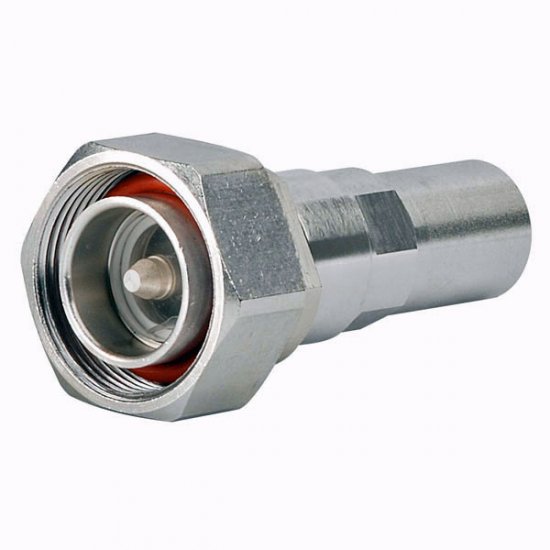
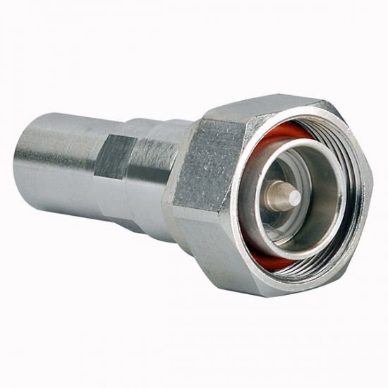
Commscope 7-16 DIN Male Positive Stop™ for 1/2 in AL4RPV-50, LDF4-50A, HL4RPV-50 cable


- Availability: In Stock
- Brand Andrews / CommScope
- Model L4TDM-PSA
- Weight: 120.09g
- SKU: L4TDM-PSA
Commscope 7-16 DIN Male Positive Stop™ for 1/2 in AL4RPV-50, LDF4-50A, HL4RPV-50 cable
Download Data Sheet
Product Classification
Product Type Wireless and radiating connector
Product Brand HELIAX® | Positive Stop™
Product Series LDF4-50A
Ordering Note CommScope® standard product (Global)
General Specifications
Body Style Straight
Cable Family AL4-50
Harmonized System (HS) Code 854420 (Coaxial cable and other coaxial electric conductors)
Inner Contact Attachment Method Captivated
Inner Contact Plating Silver
Interface 7-16 DIN Male
Mounting Angle Straight
Outer Contact Attachment Method Ring-flare
Outer Contact Plating Trimetal
Dimensions
Length 68.58 mm | 2.700 in
Diameter 34.54 mm | 1.360 in
Nominal Size 1/2 in
Outline Drawing
Click on image to enlarge.
Electrical Specifications
3rd Order IMD at Frequency -120 dBm @ 910 MHz
3rd Order IMD Test Method Two +43 dBm carriers
Insertion Loss, typical 0.05 dB
Average Power at Frequency 1.1 kW @ 900 MHz
Cable Impedance 50 ohm
Connector Impedance 50 ohm
dc Test Voltage 4000 V
Inner Contact Resistance, maximum 0.8 mOhm
Insulation Resistance, minimum 5000 mOhm
Operating Frequency Band 0 – 8800 MHz
Outer Contact Resistance, maximum 1.5 mOhm
Peak Power, maximum 40 kW
RF Operating Voltage, maximum (vrms) 1415 V
Shielding Effectiveness -110 dB
Return Loss/VSWR
Frequency Band VSWR Return Loss (dB)
45–1000 MHz 1.030 39.00
1010–2200 MHz 1.030 37.00
2200–3000 MHz 1.050 33.00
3010–4000 MHz 1.080 29.00
4010–6000 MHz 1.110 26.00
6010–8000 MHz 1.160 23.00
Mechanical Specifications
Attachment Durability 25 cycles
Connector Retention Tensile Force 889.64 N | 200.000 lbf
Connector Retention Torque 5.42 N-m | 47.998 in lb
Coupling Nut Proof Torque 25 N-m | 221.269 in lb
Coupling Nut Retention Force 1000 N | 224.810 lbf
Coupling Nut Retention Force Method MIL-C-39012C-3.25, 4.6.22
Insertion Force 200.17 N | 45.000 lbf
Insertion Force Method IEC 61169-1:15.2.4
Interface Durability 500 cycles
Interface Durability Method IEC 61169-4:9.5
Mechanical Shock Test Method MIL-STD-202, Method 213, Test Condition I
Environmental Specifications
Operating Temperature -55 °C to +85 °C (-67 °F to +185 °F)
Storage Temperature -55 °C to +85 °C (-67 °F to +185 °F)
Corrosion Test Method MIL-STD-1344A, Method 1001.1, Test Condition A
Immersion Depth 1 m
Immersion Test Mating Unmated
Immersion Test Method IEC 60529:2001, IP68
Moisture Resistance Test Method MIL-STD-202F, Method 106F
Thermal Shock Test Method MIL-STD-202F, Method 107G, Test Condition A-1, Low Temperature -55 °C
Vibration Test Method IEC 60068-2-6
Water Jetting Test Mating Unmated
Water Jetting Test Method IEC 60529:2001, IP66
Packaging and Weights
Weight, net 120.09 g | 0.265 lb


-1140x300w.jpg)


